 Viktor Deyemanns — Business Development Engineer
Modbus is a data communications protocol and has become a de facto standard protocol to connect industrial electronic devices. But how could those devices become part of the internet of things and what use cases could be developed? With this series of blog articles, we would like to give answers, ideas, suggestions, and helpful hints. To demonstrate how easy, it is to bridge the gap between devices and IT/cloud infrastructure by using Modbus Cloud Connect.
Our electrical power is usually provided by the utility as AC power, just as it comes out of the wall socket. On the consumer side of the devices and equipment connected to the power, it is not uncommon for the current to flow as DC. If there are several consumers on the DC side, it may be necessary to delineate the respective energy consumptions, e.g. for clean billing. This requires DC consumption measurement within the respective circuit.
An example of this is our technical infrastructure of the cellular network. The radio units are generally supplied with direct current. Modern data centers also operate with direct current. Battery buffers, which step in during a power failure, can also manage without converters in these cases. This results in DC systems of the appropriate size.
In e-mobility, consumption metering is of particular importance because the public e-charging stations charge with direct current. For billing (assuming calibrated measuring equipment), only the current supplied to the vehicle should be used, without the losses for conversion from the AC grid.
For our example measurement, we use measuring transducers from Socomec. The installation is done in a compact small distribution board, which allows the use at different locations.
Socomec’s Digiware series is a portfolio of different components for measuring electrical values, among other things. For each type of measurement there is a special component, e.g. for voltage and for current one module each. This allows a demand-oriented configuration for the individual application. The assembled modules are connected to each other. Finally, a system interface module is required, which supplies the individual components with power and carries out the data exchange within the setup and to the outside. In the system module all measuring data converge and are made available for the passing on over the appropriate interface. The configuration of all components can also be done in this way.
The hardware setup
In our test setup we want to measure current and voltage in a DC circuit. For both measurements one channel each is needed. The measurements are then to be transmitted through Modbus Cloud Connect via NB-IoT (Narrowband-IoT), so we need a system interface module with an RS-485 interface and Modbus RTU protocol. The composition of the main components is then as follows:
- Socomec C31 – System module with RS-485 interface
- Socomec U-31dc – voltage transducer
- Socomec U-30dc – current transmitter
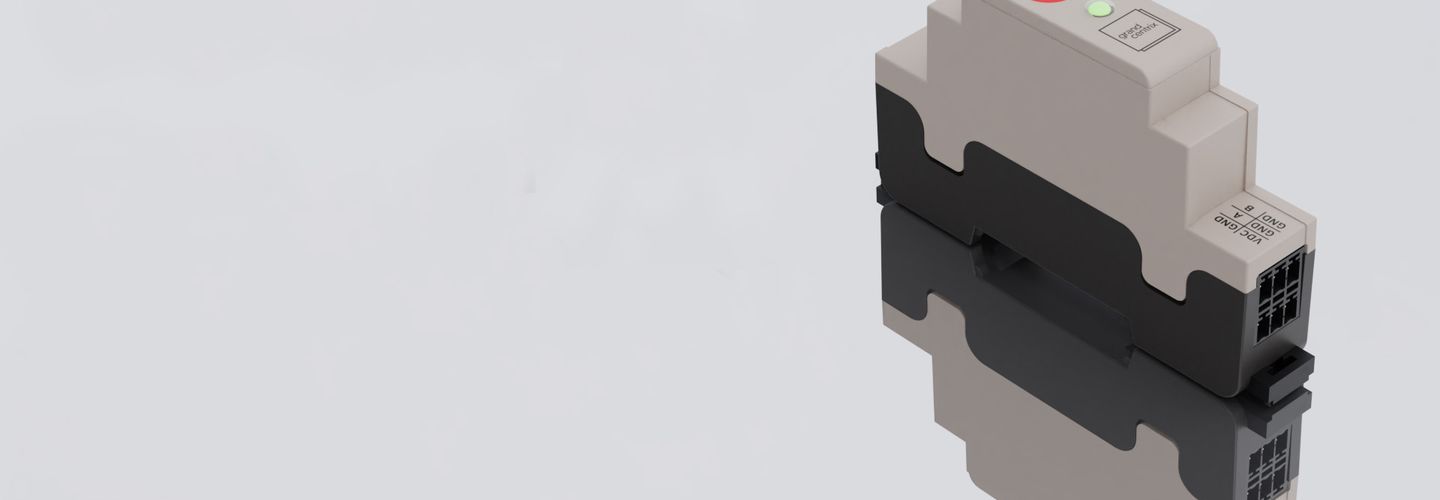
- Modbus Cloud Connect Gateway

Other components:
- Meanwell DDR-15L-24 – DC/DC power supply unitl
- A compatible current sensor
- NB-IoT adhesive antenna (accessory from Modbus Cloud Connect gateway)
- Additional passive components for module protection and electrical wiring

Configuring the Socomec modules
The initial and ongoing configuration of Socomec modules is most easily done using the Easy Config System Software. The configuration can be done for each individual module via a direct connection to the PC. The configuration can also be saved locally and applied to the next identical setup. For the external accessibility of the modules we define Modbus addresses for each module, as well as the settings for the Modbus protocol. In addition, we specify the nominal current for the selected current sensor for correct measurement. In the software, we can display the measurement data live for verification.
By combining current and voltage transducers in one system, Socomec modules automatically determine energy consumption values, which can also be queried in addition to the measurements taken directly.
Modbus Cloud Connect configuration
The Modbus Cloud Connect product is configured via the associated self-service portal. There, all devices that are associated with an account can be accessed centrally. For the configuration we need the registers of the Socomec modules. In our setup, we want to transfer the meter reading and the average of voltage, current and energy consumption. The average values are taken by the Socomec modules in a 15 minute (adjustable via the Easy Config software) cycle. In the same cycle we query and transmit the values with our Modbus Cloud Connect.
Procedure of the measurement
The setup is tested with the aid of two laboratory power supply units. One power supply unit serves as a current source without a load. A controlled short circuit is generated via the measurement connections so that the current can be variably adjusted via the power supply unit. Since the voltage approaches zero in short-circuit mode, the second power supply unit is taken as a voltage source and connected to separate measurement terminals.
For verification, the measured values can also be displayed in the software. Not only current and voltage are displayed as measured values, but also the energy values that can be derived from them.
End-to-end set-up of the DC measuring device
The Socmec unit now measures voltage and current and there is a transmission of the measured values via the Modbus Cloud Connect product. In the Modbus Cloud Connect self-service portal, a cloud adapter can now be set to forward the data to the desired endpoint. This can be a visualization platform, for example, from our partners Device Insight or Datacake.
The Socomec measuring device supplemented by Modbus Cloud Connect and Datacake is thus connected end-to-end. All required measurement data is transmitted as needed and is available in visualized form. The combination of a measuring device and Modbus Cloud Connect thus represents an ideal solution for submetering - also on the DC side.
Modbus Cloud Connect makes it easy to use, flexibly connectable and broadly applicable. Your device, directly to the cloud.