
 Dipl.-Ing. Sebastian Tode — Teamlead Embedded Hardware
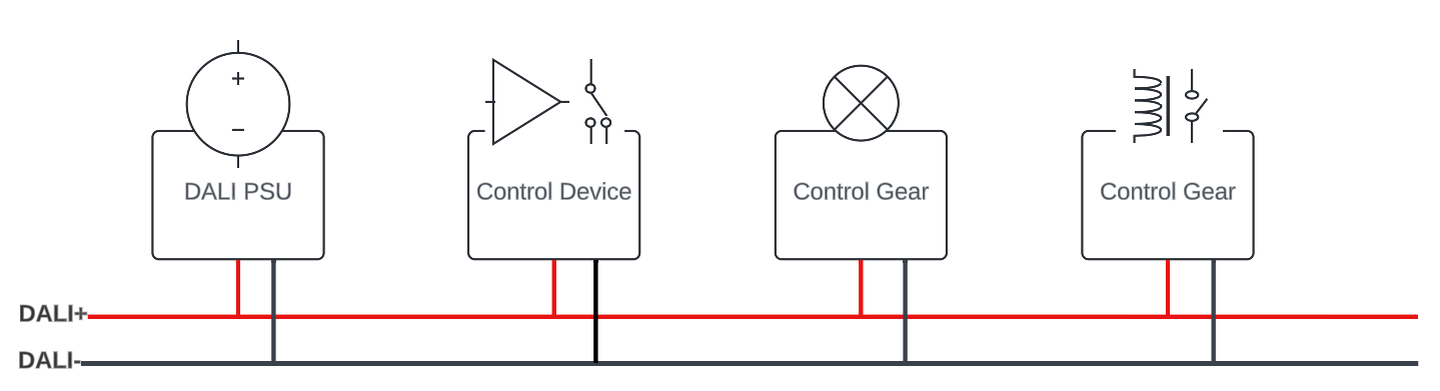
Shown above are: a power supply unit (PSU) that supplies the bus with power, a control device that accepts inputs or records sensor data, and two control gears which are either a luminaire ballast themselves or control a luminaire via a relay contact.
DALI connects luminaires, sensors and switches via a two-wire bus, which transmits digital information between them, and at the same time provides power to their transceiver frontends. That way control gear like sensors and buttons with a low current consumption do not need a separate power supply. Luminaires on the other hand still depend on a separate AC line voltage supply, that is why DALI installations are typically connected with a 5-wire cable.
To make sure all members of the installation work perfectly together, certain standards were defined by the DALI Alliance. Designing hardware meeting these standards can be quite challenging, so here are the most important pitfalls to consider.
Electrical Safety
Since DALI installations typically run 5-wire cables there is a high risk that 230 VAC line voltage is mistakenly connected to the DALI bus terminals. To prevent any damage we need a protection circuit for that case. Furthermore the applicable safety norm specifies a reinforced isolation in form of a galvanic decoupling between a potential 230 VAC source and any user accessible parts of the device i.e. a USB or Ethernet jack. Even though Ethernet itself has a galvanic decoupling we still need to look at the isolation voltage. Standard Ethernet jacks with integrated magnetics (Magjacks) only provide an isolation of 1,5 kV which is not sufficient for reinforced isolation in that case. The correct value for the isolation voltage depends on the environment your device will be used in, so make sure to specify that early in the design process and write down a concept for electrical safety.
Polarity
The connection terminals of a DALI control gear or a DALI control device without an integrated DALI PSU are interchangeable, and therefore both marked with “DA”. To implement this in hardware, a bridge rectifier has to be placed between the DALI bus terminals and the transceiver circuit. Additionally the transceiver frontend needs a galvanic decoupling from the rest of the circuit, which is usually done with an optocoupler. If the optocoupler is the only galvanic decoupling component between the DALI bus and user accessible parts it has to meet the electrical safety demands mentioned earlier.
Slew Rate
To make DALI work on long cable runs the communication protocol is rather slow (1.2 kBaud). That way the signals do not need high slew rates, which also minimizes ringing and radiated emission. The DALI standard specifies rise and fall times of 3 to 15µs. What sounds like a simplification of the circuit’s demands turns out to be quite tricky, as modern semiconductors tend to switch quite fast, mostly in the range of nanoseconds.
That means one has to select a transistor with a very long switching time, or one needs to slow it down with external components. The latter approach is the better one, as finding a slow transistor can be time consuming, and limits you to a low number of components to choose from.
For lower slew rates through external components four approaches will come into the engineer’s mind:
- Using a weak driver, i.e. a bipolar transistor driven with a low base current. This approach goes contrary to the DALI specification of a maximum power supply current of 250 mA. That means that every transmitter on the bus must be able to pull the 250 mA supply low. It will be tough to balance that out with a correct slew rate and will result in a sensitive part of your design that might be susceptible to temperature changes.
- Adding capacitance to the transistor base.


Adding capacitance to the base extends the propagation delay between the signal coming from the microcontroller and the signal on the DALI bus. If the propagation delay gets too long it will cause framing errors on the DALI bus.
- Adding capacitance to the DALI Bus terminals
Adding capacitance directly to the DALI bus is very much limited by spec as one has to make sure the parallel capacitance of all participants on the bus does not distort the signal. To prevent any issues here you should not use any values higher than the lower nF range. This is usually not enough to slow down the transmitted signal sufficiently.
- Adding a capacitor between base and collector. This scenario is simulated in Fig.3.
That works! But let’s also check what happens at the transmitter by the time a signal is received. Fig. 4 shows a simulation how the same circuit reacts to a signal on the DALI bus.
Now the external signal passes through the capacitor C3 and is present at Tx with an amplitude far above CMOS level. Depending on how the rest of the transmitter circuit is designed this can cause damage to the components or distortions on the DALI bus signal itself. To prevent that a forward directed diode between DALI+ and the transmitter’s collector can help, or a well chosen capacitor value that limits current draw.
Response Time
The DALI specification requires all devices to respond to a DALI command within a defined timing period. If you want to run a DALI stack directly in an embedded Linux environment you are in bad luck as Linux is not designed for real time applications. Therefore it is a good approach to run at least the DALI low level driver on a companion microcontroller or a real time core on top of any sort of RTOS or bare metal code.
Supply Current Limit of a DALI Gear
Since there can be up to 64 bus participants there is a current limit of 2 mA every DALI bus device is allowed to draw from the bus in idle state. Make sure to design your transceiver circuit to match.
Switching Voltage Levels
The DALI standard defines high and low level switching voltage ranges for both the receiver and the transmitter. The receiver voltages are pretty straightforward to design a circuit for. Mostly this is done with a Zener diode / voltage divider combination or a comparator. The latter might interfere with the maximum current draw specification mentioned earlier. The transmitter voltage levels require a closer look though. A transmitter must be able to pull the DALI bus down to at least 4.5 V. While that sounds easy, you have to take the voltage drop over the bridge rectifier and the line voltage protection into account, which quickly consumes up to 2 V. Balancing out slew rate and drive strength it is quite likely that you get close to 4.5 V.
Conclusion
We can summarize the following: the Digital Addressable Lighting Interface (DALI) has established itself as the technical standard for connecting lighting components flexibly and digitally in practice.
The DALI Alliance defines specific standards to ensure error-free interaction between components. The development of hardware that complies with these standards poses several challenges, including:
- Electrical safety: A well thought-out concept for electrical safety is essential. Protection against accidentally applied mains voltage must also be considered. In many cases, galvanic decoupling using optocouplers is a solution.
- Polarity: A bridge rectifier provides the reverse polarity protection required by the standard.
- Slew rate: Rise and fall times of 3 to 15 µs must be maintained, which requires the selection and adaptation of suitable transistors and external components.
- Response time: Devices must respond to DALI commands within a certain time. Real-time capability in an embedded Linux environment can be ensured by co-processors or RTOS.
- Supply current limit: Each DALI bus device may only draw a maximum of 2 mA in idle state.
- Switching voltage level: Precise voltage levels are required for the HIGH and LOW states, whereby the voltage drop across various components must be taken into account.
By understanding and considering these challenges, reliable and standard-compliant DALI hardware solutions can be developed that enable efficient and safe lighting control in buildings.
Find out here what the DALI standard in hardware development means.